

How To Access Accelerometer Registers
In this tutorial we will larn how to utilise the MPU6050 Accelerometer and Gyroscope sensor with the Arduino. First, I will explain how the MPU6050 works and how to read the data from it, and and then we will make 2 practical examples.
You can watch the post-obit video or read the written tutorial beneath.
Overview
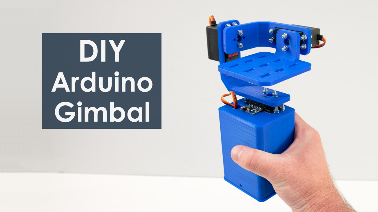
In the get-go instance, using the Processing evolution surround, nosotros will make a 3D visualization of the sensor orientation, and in the second example we will brand a uncomplicated self-stabilizing platform or a DIY Gimbal. Based on the MPU6050 orientation and its fused accelerometer and gyroscope data, nosotros control the three servos that keep the platform level.
How It Works
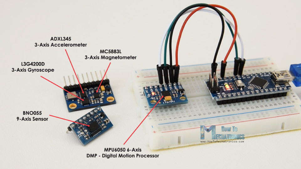
The MPU6050 IMU has both iii-Centrality accelerometer and 3-Axis gyroscope integrated on a single chip.
The gyroscope measures rotational velocity or rate of alter of the angular position over time, along the X, Y and Z centrality. It uses MEMS technology and the Coriolis Effect for measuring, but for more details on information technology you can check my particular How MEMS Sensors Piece of work tutorial. The outputs of the gyroscope are in degrees per second, so in order to get the angular position we only need to integrate the angular velocity.
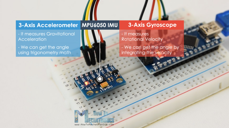
On the other mitt, the MPU6050 accelerometer measures dispatch in the aforementioned way as explained in the previous video for the ADXL345 accelerometer sensor. Briefly, it can measure out gravitational acceleration along the three axes and using some trigonometry math we can calculate the bending at which the sensor is positioned. So, if we fuse, or combine the accelerometer and gyroscope data we can get very authentic data almost the sensor orientation.
The MPU6050 IMU is as well called 6-axis motion tracking device or 6 DoF (six Degrees of Liberty) device, considering of its vi outputs, or the 3 accelerometer outputs and the 3 gyroscope outputs.
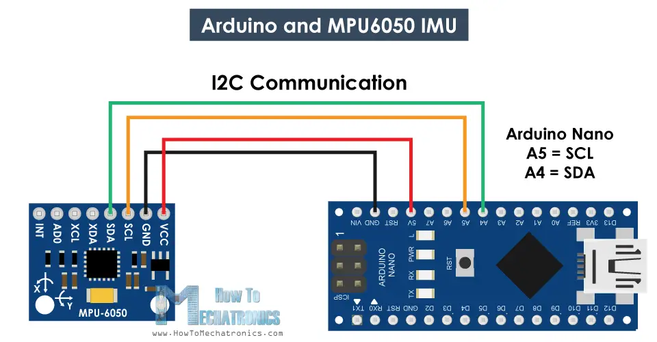
Arduino and MPU6050
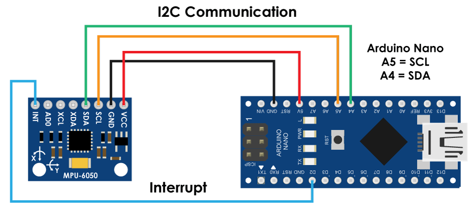
Let'south have a look how nosotros can connect and read the data from the MPU6050 sensor using the Arduino. We are using the I2C protocol for communication with the Arduino and so we need only two wires for connecting it, plus the two wires for powering.
Y'all can get the components needed for this Arduino Tutorial from the links below:
- MPU6050 IMU …………………………..…. Amazon /Banggood / AliExpress
- Arduino Board ………………………….….. Amazon / Banggood / AliExpress
- Breadboard and Leap Wires …………Amazon / Banggood / AliExpress
Disclosure: These are affiliate links. Equally an Amazon Associate I earn from qualifying purchases.
MPU6050 Arduino Code
Here's the Arduino lawmaking for reading the information from the MPU6050 sensor. Below the code you can find a detail clarification of it.
/* Arduino and MPU6050 Accelerometer and Gyroscope Sensor Tutorial past Dejan, https://howtomechatronics.com */ #include <Wire.h> const int MPU = 0x68; // MPU6050 I2C accost float AccX, AccY, AccZ; float GyroX, GyroY, GyroZ; float accAngleX, accAngleY, gyroAngleX, gyroAngleY, gyroAngleZ; bladder roll, pitch, yaw; bladder AccErrorX, AccErrorY, GyroErrorX, GyroErrorY, GyroErrorZ; float elapsedTime, currentTime, previousTime; int c = 0; void setup () { Serial.begin(19200); Wire.begin(); // Initialize comunication Wire.beginTransmission(MPU); // Start communication with MPU6050 // MPU=0x68 Wire.write(0x6B); // Talk to the register 6B Wire.write(0x00); // Make reset - identify a 0 into the 6B annals Wire.endTransmission(true); //end the transmission /* // Configure Accelerometer Sensitivity - Full Scale Range (default +/- 2g) Wire.beginTransmission(MPU); Wire.write(0x1C); //Talk to the ACCEL_CONFIG register (1C hex) Wire.write(0x10); //Set up the annals bits as 00010000 (+/- 8g full calibration range) Wire.endTransmission(true); // Configure Gyro Sensitivity - Full Scale Range (default +/- 250deg/s) Wire.beginTransmission(MPU); Wire.write(0x1B); // Talk to the GYRO_CONFIG annals (1B hex) Wire.write(0x10); // Set the register $.25 as 00010000 (1000deg/south full scale) Wire.endTransmission(truthful); delay(20); */ // Telephone call this function if yous need to get the IMU error values for your module calculate_IMU_error(); delay(twenty); } void loop () { // === Read acceleromter data === // Wire.beginTransmission(MPU); Wire.write(0x3B); // Showtime with annals 0x3B (ACCEL_XOUT_H) Wire.endTransmission(false); Wire.requestFrom(MPU, 6, truthful); // Read 6 registers total, each axis value is stored in ii registers //For a range of +-2g, we demand to carve up the raw values past 16384, according to the datasheet AccX = (Wire.read() << viii | Wire.read()) / 16384.0; // X-axis value AccY = (Wire.read() << 8 | Wire.read()) / 16384.0; // Y-axis value AccZ = (Wire.read() << viii | Wire.read()) / 16384.0; // Z-axis value // Calculating Roll and Pitch from the accelerometer information accAngleX = (atan(AccY / sqrt(pow(AccX, 2) + pow(AccZ, 2))) * 180 / PI) - 0.58; // AccErrorX ~(0.58) See the calculate_IMU_error()custom function for more details accAngleY = (atan(-one * AccX / sqrt(pw(AccY, 2) + pw(AccZ, ii))) * 180 / PI) + 1.58; // AccErrorY ~(-ane.58) // === Read gyroscope data === // previousTime = currentTime; // Previous time is stored before the actual time read currentTime = millis(); // Current time actual time read elapsedTime = (currentTime - previousTime) / g; // Divide by g to become seconds Wire.beginTransmission(MPU); Wire.write(0x43); // Gyro information commencement register address 0x43 Wire.endTransmission(false); Wire.requestFrom(MPU, six, true); // Read four registers total, each centrality value is stored in 2 registers GyroX = (Wire.read() << 8 | Wire.read()) / 131.0; // For a 250deg/due south range we have to carve up kickoff the raw value by 131.0, according to the datasheet GyroY = (Wire.read() << 8 | Wire.read()) / 131.0; GyroZ = (Wire.read() << eight | Wire.read()) / 131.0; // Correct the outputs with the calculated mistake values GyroX = GyroX + 0.56; // GyroErrorX ~(-0.56) GyroY = GyroY - 2; // GyroErrorY ~(2) GyroZ = GyroZ + 0.79; // GyroErrorZ ~ (-0.8) // Currently the raw values are in degrees per seconds, deg/southward, so we need to multiply by sendonds (s) to get the angle in degrees gyroAngleX = gyroAngleX + GyroX * elapsedTime; // deg/s * s = deg gyroAngleY = gyroAngleY + GyroY * elapsedTime; yaw = yaw + GyroZ * elapsedTime; // Complementary filter - combine acceleromter and gyro angle values roll = 0.96 * gyroAngleX + 0.04 * accAngleX; pitch = 0.96 * gyroAngleY + 0.04 * accAngleY; // Print the values on the series monitor Serial.impress(curlicue); Serial.print("/"); Serial.print(pitch); Serial.print("/"); Serial.println(yaw); } void calculate_IMU_error () { // We can call this funtion in the setup section to calculate the accelerometer and gyro information error. From here nosotros will get the error values used in the above equations printed on the Series Monitor. // Notation that we should identify the IMU flat in society to get the proper values, and so that we then tin the correct values // Read accelerometer values 200 times while (c < 200) { Wire.beginTransmission(MPU); Wire.write(0x3B); Wire.endTransmission(false); Wire.requestFrom(MPU, 6, truthful); AccX = (Wire.read() << 8 | Wire.read()) / 16384.0 ; AccY = (Wire.read() << viii | Wire.read()) / 16384.0 ; AccZ = (Wire.read() << 8 | Wire.read()) / 16384.0 ; // Sum all readings AccErrorX = AccErrorX + ((atan((AccY) / sqrt(pw((AccX), ii) + pw((AccZ), 2))) * 180 / PI)); AccErrorY = AccErrorY + ((atan(-1 * (AccX) / sqrt(pow((AccY), 2) + prisoner of war((AccZ), 2))) * 180 / PI)); c++; } //Divide the sum by 200 to go the error value AccErrorX = AccErrorX / 200; AccErrorY = AccErrorY / 200; c = 0; // Read gyro values 200 times while (c < 200) { Wire.beginTransmission(MPU); Wire.write(0x43); Wire.endTransmission(false); Wire.requestFrom(MPU, 6, true); GyroX = Wire.read() << 8 | Wire.read(); GyroY = Wire.read() << 8 | Wire.read(); GyroZ = Wire.read() << 8 | Wire.read(); // Sum all readings GyroErrorX = GyroErrorX + (GyroX / 131.0); GyroErrorY = GyroErrorY + (GyroY / 131.0); GyroErrorZ = GyroErrorZ + (GyroZ / 131.0); c++; } //Divide the sum by 200 to get the fault value GyroErrorX = GyroErrorX / 200; GyroErrorY = GyroErrorY / 200; GyroErrorZ = GyroErrorZ / 200; // Print the fault values on the Serial Monitor Serial.impress("AccErrorX: "); Serial.println(AccErrorX); Serial.print("AccErrorY: "); Serial.println(AccErrorY); Serial.print("GyroErrorX: "); Serial.println(GyroErrorX); Serial.print("GyroErrorY: "); Serial.println(GyroErrorY); Serial.impress("GyroErrorZ: "); Serial.println(GyroErrorZ); }
Code language: Arduino ( arduino ) Code Clarification: So starting time we need to include the Wire.h library which is used for the I2C communication and define some variables needed storing the data.
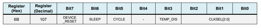
In the setup section, we demand initialize the wire library and reset the sensor through the power management annals. In order to practice that we demand to take a wait at the datasheet of the sensor from where we can run into the register address.
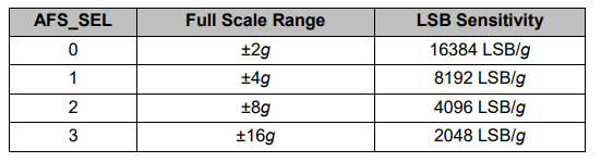
Too, if nosotros want, we can select the Full-Scale Range for the accelerometer and the gyroscope using their configuration registers. For this example, we will employ the default +- 2g range for the accelerometer and 250 degrees/s range for the gyroscope, and so I volition go out this part of the code commented.
// Configure Accelerometer Sensitivity - Full Scale Range (default +/- 2g) Wire.beginTransmission(MPU); Wire.write(0x1C); //Talk to the ACCEL_CONFIG register (1C hex) Wire.write(0x10); //Fix the register bits every bit 00010000 (+/- 8g total calibration range) Wire.endTransmission(truthful); // Configure Gyro Sensitivity - Full Scale Range (default +/- 250deg/s) Wire.beginTransmission(MPU); Wire.write(0x1B); // Talk to the GYRO_CONFIG register (1B hex) Wire.write(0x10); // Set the register bits as 00010000 (1000deg/s full scale) Wire.endTransmission(true); */
Code linguistic communication: Arduino ( arduino ) In the loop section we first by reading the accelerometer information. The information for each axis is stored in ii bytes or registers and nosotros can encounter the addresses of these registers from the datasheet of the sensor.
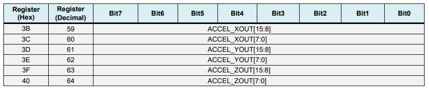
In club to read them all, we start with the first register, and using the requiestFrom() function we asking to read all half-dozen registers for the X, Y and Z axes. Then nosotros read the data from each annals, and considering the outputs are twos complement, we combine them accordingly to get the correct values.
// === Read acceleromter data === // Wire.beginTransmission(MPU); Wire.write(0x3B); // Commencement with register 0x3B (ACCEL_XOUT_H) Wire.endTransmission(faux); Wire.requestFrom(MPU, six, true); // Read half dozen registers full, each axis value is stored in 2 registers //For a range of +-2g, nosotros need to divide the raw values by 16384, co-ordinate to the datasheet AccX = (Wire.read() << viii | Wire.read()) / 16384.0; // 10-axis value AccY = (Wire.read() << 8 | Wire.read()) / 16384.0; // Y-axis value AccZ = (Wire.read() << eight | Wire.read()) / 16384.0; // Z-axis value
Lawmaking language: Arduino ( arduino ) In social club to go output values from -1g to +1g, suitable for calculating the angles, nosotros divide the output with the previously selected sensitivity.
Finally, using these two formulas, we calculate the scroll and pitch angles from the accelerometer data.
// Calculating Gyre and Pitch from the accelerometer data accAngleX = (atan(AccY / sqrt(pow(AccX, 2) + pow(AccZ, ii))) * 180 / PI) - 0.58; // AccErrorX ~(0.58) Encounter the calculate_IMU_error()custom function for more than details accAngleY = (atan(-1 * AccX / sqrt(pow(AccY, two) + pow(AccZ, two))) * 180 / PI) + 1.58; // AccErrorY ~(-ane.58)
Code language: Arduino ( arduino ) Side by side, using the aforementioned method we get the gyroscope information.
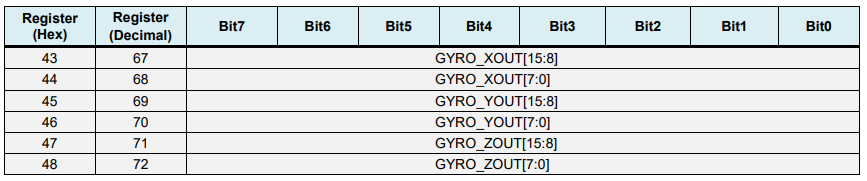
Nosotros read the 6 gyroscope registers, combine their information appropriately and divide it past the previously selected sensitivity in order to get the output in degrees per second.
// === Read gyroscope data === // previousTime = currentTime; // Previous time is stored earlier the bodily time read currentTime = millis(); // Current time actual time read elapsedTime = (currentTime - previousTime) / thou; // Carve up past 1000 to get seconds Wire.beginTransmission(MPU); Wire.write(0x43); // Gyro information kickoff annals accost 0x43 Wire.endTransmission(false); Wire.requestFrom(MPU, 6, true); // Read 4 registers total, each axis value is stored in 2 registers GyroX = (Wire.read() << 8 | Wire.read()) / 131.0; // For a 250deg/southward range we take to dissever first the raw value by 131.0, according to the datasheet GyroY = (Wire.read() << 8 | Wire.read()) / 131.0; GyroZ = (Wire.read() << 8 | Wire.read()) / 131.0;
Code language: Arduino ( arduino ) 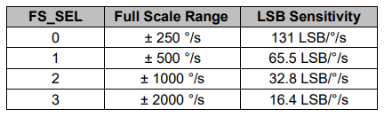
Here you can notice that I correct the output values with some small calculated error values, which I will explain how nosotros get them in a minute. So as the outputs are in degrees per second, now we need to multiply them with the time to get just degrees. The time value is captured before each reading iteration using the millis() function.
// Correct the outputs with the calculated fault values GyroX = GyroX + 0.56; // GyroErrorX ~(-0.56) GyroY = GyroY - 2; // GyroErrorY ~(ii) GyroZ = GyroZ + 0.79; // GyroErrorZ ~ (-0.8) // Currently the raw values are in degrees per seconds, deg/due south, then nosotros demand to multiply by sendonds (s) to get the angle in degrees gyroAngleX = gyroAngleX + GyroX * elapsedTime; // deg/s * southward = deg gyroAngleY = gyroAngleY + GyroY * elapsedTime; yaw = yaw + GyroZ * elapsedTime;
Code language: Arduino ( arduino ) Finally, we fuse the accelerometer and the gyroscope data using a complementary filter. Hither, nosotros accept 96% of the gyroscope data because information technology is very authentic and doesn't suffer from external forces. The downward side of the gyroscope is that it drifts, or it introduces error in the output as the time goes on. Therefore, on the long term, we use the information from the accelerometer, 4% in this case, enough to eliminate the gyroscope drift fault.
// Complementary filter - combine acceleromter and gyro bending values roll = 0.96 * gyroAngleX + 0.04 * accAngleX; pitch = 0.96 * gyroAngleY + 0.04 * accAngleY;
Code language: Arduino ( arduino ) Withal, as we cannot calculate the Yaw from the accelerometer data, we cannot implement the complementary filter on it.
Before we accept a look at the results, let me quickly explain how to go the mistake correction values. For calculate these errors nosotros can call the calculate_IMU_error() custom function while the sensor is in flat still position. Here nosotros do 200 readings for all outputs, nosotros sum them and carve up them by 200. As we are holding the sensor in flat nonetheless position, the expected output values should exist 0. So, with this calculation nosotros can become the average error the sensor makes.
void calculate_IMU_error () { // We tin can phone call this funtion in the setup section to calculate the accelerometer and gyro information error. From hither nosotros will go the error values used in the above equations printed on the Serial Monitor. // Annotation that we should identify the IMU flat in order to get the proper values, so that we and then can the correct values // Read accelerometer values 200 times while (c < 200) { Wire.beginTransmission(MPU); Wire.write(0x3B); Wire.endTransmission(faux); Wire.requestFrom(MPU, six, true); AccX = (Wire.read() << 8 | Wire.read()) / 16384.0 ; AccY = (Wire.read() << 8 | Wire.read()) / 16384.0 ; AccZ = (Wire.read() << 8 | Wire.read()) / 16384.0 ; // Sum all readings AccErrorX = AccErrorX + ((atan((AccY) / sqrt(prisoner of war((AccX), ii) + pow((AccZ), 2))) * 180 / PI)); AccErrorY = AccErrorY + ((atan(-1 * (AccX) / sqrt(pw((AccY), ii) + pow((AccZ), 2))) * 180 / PI)); c++; } //Divide the sum by 200 to get the fault value AccErrorX = AccErrorX / 200; AccErrorY = AccErrorY / 200; c = 0; // Read gyro values 200 times while (c < 200) { Wire.beginTransmission(MPU); Wire.write(0x43); Wire.endTransmission(false); Wire.requestFrom(MPU, 6, truthful); GyroX = Wire.read() << eight | Wire.read(); GyroY = Wire.read() << eight | Wire.read(); GyroZ = Wire.read() << 8 | Wire.read(); // Sum all readings GyroErrorX = GyroErrorX + (GyroX / 131.0); GyroErrorY = GyroErrorY + (GyroY / 131.0); GyroErrorZ = GyroErrorZ + (GyroZ / 131.0); c++; } //Divide the sum by 200 to get the error value GyroErrorX = GyroErrorX / 200; GyroErrorY = GyroErrorY / 200; GyroErrorZ = GyroErrorZ / 200; // Print the error values on the Serial Monitor Serial.print("AccErrorX: "); Serial.println(AccErrorX); Serial.print("AccErrorY: "); Serial.println(AccErrorY); Series.impress("GyroErrorX: "); Serial.println(GyroErrorX); Serial.print("GyroErrorY: "); Series.println(GyroErrorY); Serial.impress("GyroErrorZ: "); Serial.println(GyroErrorZ); }
Code language: Arduino ( arduino ) Nosotros but impress the values on the series monitor and once we know them, we can implement them in the code as shown before, for both the roll and pitch calculation, equally well every bit for the 3 gyroscope outputs.
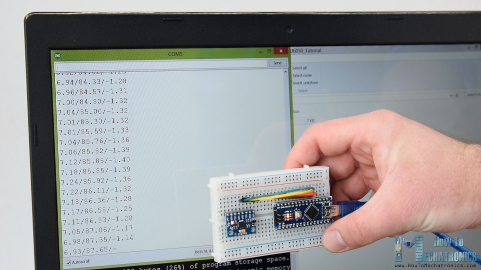
Finally, using the Serial.print function we can print the Roll, Pitch and Yaw values on the serial monitor and see whether the sensor works properly.
MPU6050 Orientation Tracking – 3D Visualization
Next, in guild to make the 3D visualization example nosotros simply need take this data the Arduino is sending through the serial port in the Processing evolution environment. Hither'due south the consummate Processing lawmaking:
/* Arduino and MPU6050 IMU - 3D Visualization Instance past Dejan, https://howtomechatronics.com */ import processing.series.*; import java.awt.consequence.KeyEvent; import java.io.IOException; Serial myPort; Cord information=""; float ringlet, pitch,yaw; void setup () { size (2560, 1440, P3D); myPort = new Series(this, "COM7", 19200); // starts the serial communication myPort.bufferUntil('\n'); } void describe () { translate(width/2, height/2, 0); background(233); textSize(22); text("Roll: " + int(ringlet) + " Pitch: " + int(pitch), -100, 265); // Rotate the object rotateX(radians(-pitch)); rotateZ(radians(roll)); rotateY(radians(yaw)); // 3D 0bject textSize(30); fill(0, 76, 153); box (386, 40, 200); // Draw box textSize(25); fill(255, 255, 255); text("www.HowToMechatronics.com", -183, 10, 101); //delay(10); //println("ypr:\t" + angleX + "\t" + angleY); // Impress the values to check whether nosotros are getting proper values } // Read data from the Series Port void serialEvent (Serial myPort) { // reads the data from the Serial Port up to the graphic symbol '.' and puts it into the String variable "data". data = myPort.readStringUntil('\northward'); // if you got any bytes other than the linefeed: if (data != null) { information = trim(data); // split the cord at "/" Cord items[] = split(data, '/'); if (items.length > one) { //--- Gyre,Pitch in degrees scroll = float(items[0]); pitch = float(items[1]); yaw = float(items[2]); } } }
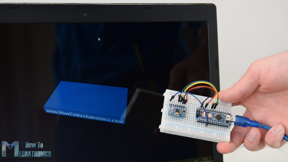
Lawmaking language: Arduino ( arduino ) Here we read the incoming data from the Arduino and put it into the appropriate Roll, Pitch and Yaw variables. In the master draw loop, we employ these values to rotate the 3D object, in this case that's a simple box with a particular color and text on it.
If we run the sketch, we can see how good the MPU6050 sensor is for tracking orientation. The 3D object tracks the orientation of the sensor quite accurate and it's likewise very responsive.
As I mentioned, the only down side is that the Yaw will migrate over time considering nosotros cannot use the complementary filter for it. For improving this we need to use an additional sensor. That'due south usually a magnetometer which can exist used as a long-term correction for the gyroscope Yaw drift. However, the MPU6050 actually have a feature that'south called Digital Motion Processor which is used for onboard calculations of the data and information technology's capable of eliminating the Yaw drift.
Here'due south the same 3D example with the Digital Movement Processor in utilise. We can see how accurate the orientation tracking is at present, without the Yaw drift. The onboard processor tin likewise calculate and output Quaternions which are used for representing orientations and rotations of objects in three dimensions. In this instance we are actually using quaternions for representing the orientation which as well doesn't endure from Gimbal lock which occurs when using Euler angles.
Nevertheless, getting this information from the sensor is a bit more complicated than what nosotros explained before. Outset of all, nosotros need to connect and additional wire to an Arduino digital pivot. That's an interrupt pin which is used for reading this information blazon from the MPU6050.
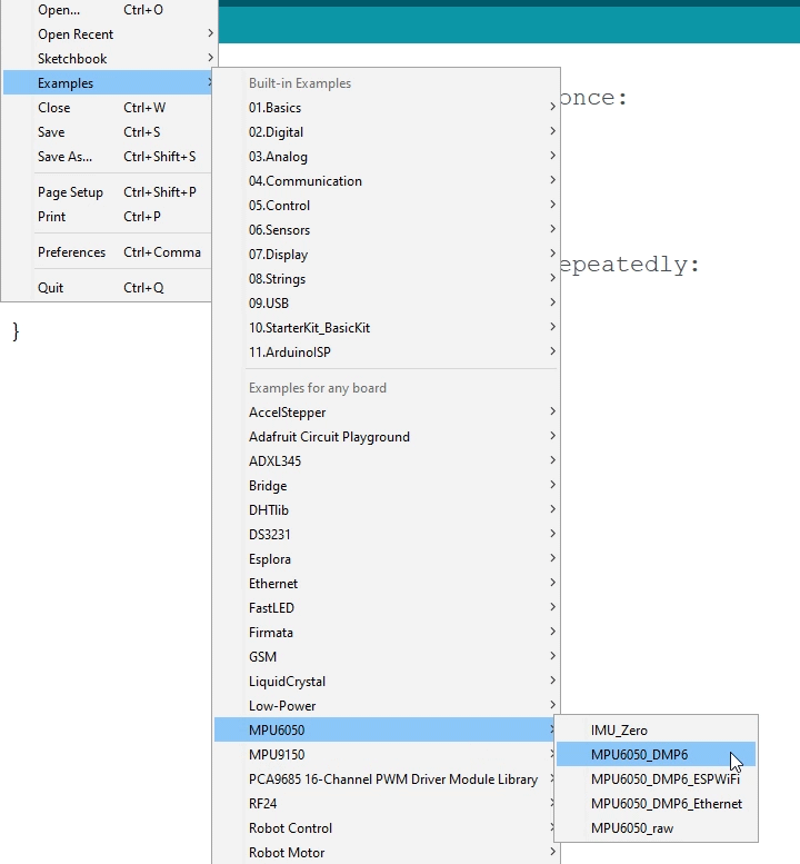
The lawmaking is also a bit more complicated so that's why we are going to use the i2cdevlib library by Jeff Rowberg. This library tin can be downloaded from GitHub and I will include a link to in on the website article.
Once we install the library, we tin open the MPU6050_DMP6 case from the library. This instance is well explained with comments for each line.
Hither we tin select what kind of output we want, quaternions, Euler angles, yaw, pitch and roll, accelerations value or quaternions for the 3D visualization. This library also includes a Processing sketch for the 3D visualization example. I just modified it to get the box shape equally in the previous instance. Hither'south the 3D visualization Processing code that works with the MPU6050_DPM6 case, for selected "OUTPUT_TEAPOT" output:
/* Arduino and MPU6050 IMU - 3D Visualization Example past Dejan, https://howtomechatronics.com */ import processing.serial.*; import coffee.awt.event.KeyEvent; import java.io.IOException; Serial myPort; String information=""; float roll, pitch,yaw; void setup () { size (2560, 1440, P3D); myPort = new Serial(this, "COM7", 19200); // starts the series communication myPort.bufferUntil('\north'); } void draw () { translate(width/2, height/2, 0); background(233); textSize(22); text("Roll: " + int(roll) + " Pitch: " + int(pitch), -100, 265); // Rotate the object rotateX(radians(-pitch)); rotateZ(radians(roll)); rotateY(radians(yaw)); // 3D 0bject textSize(30); fill(0, 76, 153); box (386, 40, 200); // Draw box textSize(25); fill(255, 255, 255); text("www.HowToMechatronics.com", -183, ten, 101); //delay(10); //println("ypr:\t" + angleX + "\t" + angleY); // Print the values to check whether nosotros are getting proper values } // Read data from the Serial Port void serialEvent (Series myPort) { // reads the information from the Serial Port up to the graphic symbol '.' and puts it into the Cord variable "information". data = myPort.readStringUntil('\due north'); // if you lot got whatever bytes other than the linefeed: if (information != null) { data = trim(information); // separate the string at "/" Cord items[] = split(information, '/'); if (items.length > 1) { //--- Roll,Pitch in degrees gyre = bladder(items[0]); pitch = bladder(items[1]); yaw = float(items[2]); } } }
Code language: Arduino ( arduino ) So here using the serialEvent() function we receive the quaternions coming from the Arduino, and in the master describe loop we apply them to rotate the 3D object. If nosotros run the sketch, nosotros can see how good quaternions are for rotating objects in three dimensions.
In order not to overload this tutorial, I placed the 2nd case, the DIY Arduino Gimbal or Self-Stabilizing platform, on a separate commodity.
Feel free to ask any question related to this tutorial in the comments section below and too don't forget to check my collection of Arduino Projects.

Source: https://howtomechatronics.com/tutorials/arduino/arduino-and-mpu6050-accelerometer-and-gyroscope-tutorial/
Posted by: watlingtonthestive.blogspot.com
0 Response to "How To Access Accelerometer Registers"
Post a Comment